I started with this diagram, and found it was difficult with the wild stuff on the switch.

As this was not working, I went to this diagram, which simplifies things at the switch, but adds the need to run a ground wire, which I understood was unnecessary with actives.
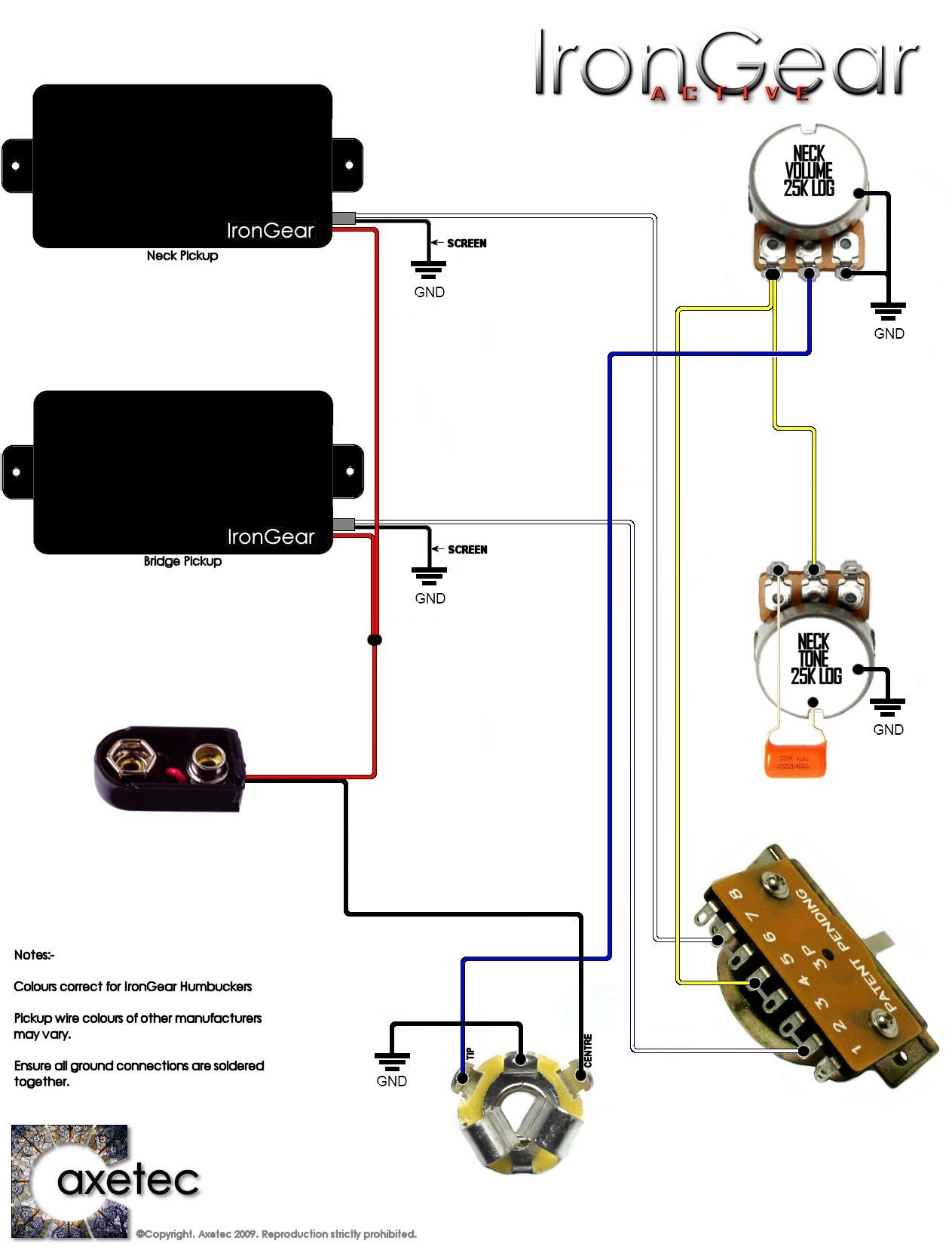
When I try to check the wiring (none of the pots or switches actually inserted into their holes, I get noise and radio signals, which are not the nice, quiet actives that I want. Do I need a ground? Does either diagram make sense?
I may bust out the wick and the solder sucker and redo the whole thing. Or buy a set of passives and give up.