Page 1 of 1
More soldering....GAAAAAH!
Posted: Sun Jun 28, 2020 11:01 am
by Rollin Hand
Ok, trying to wire up a set of cheap actives in my Spad and....I just can't seem to do it. It's 2 hums, 1v 1t and a three way blade.
I started with this diagram, and found it was difficult with the wild stuff on the switch.

As this was not working, I went to this diagram, which simplifies things at the switch, but adds the need to run a ground wire, which I understood was unnecessary with actives.
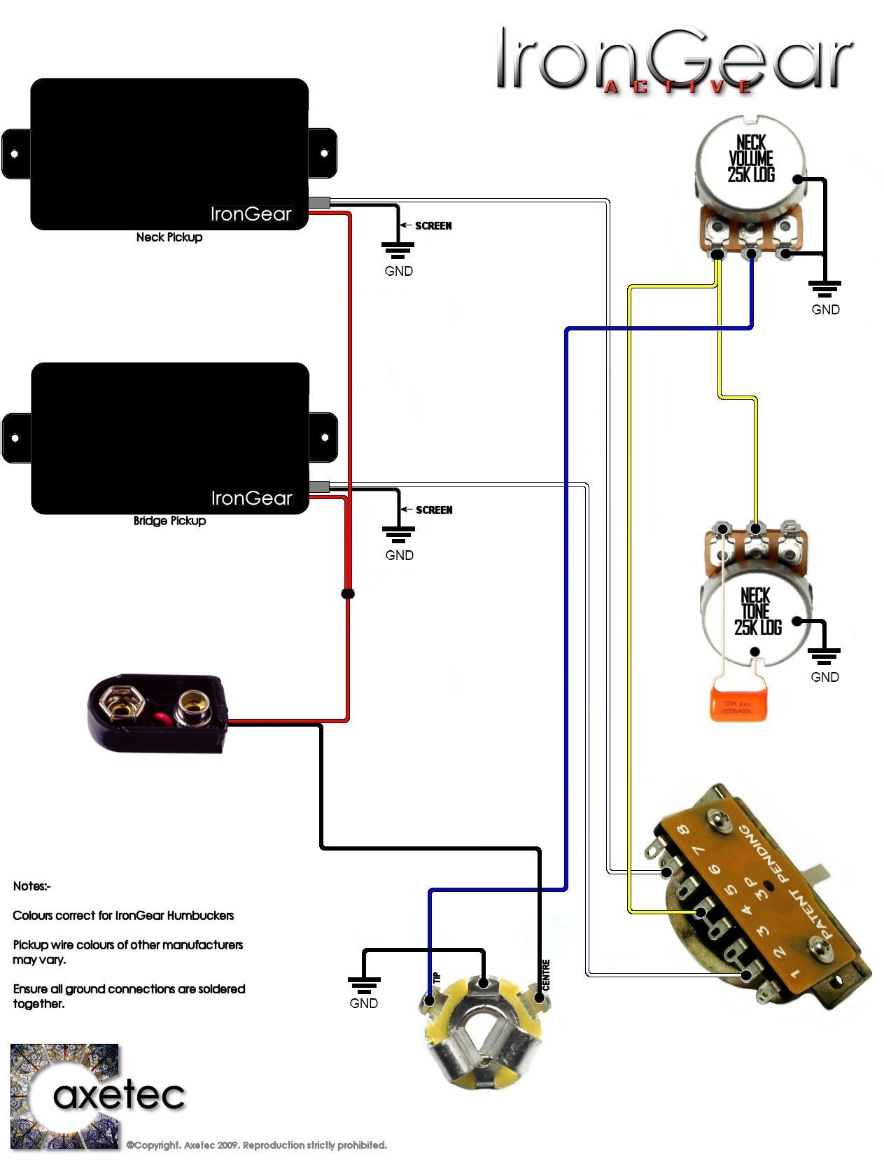
When I try to check the wiring (none of the pots or switches actually inserted into their holes, I get noise and radio signals, which are not the nice, quiet actives that I want. Do I need a ground? Does either diagram make sense?
I may bust out the wick and the solder sucker and redo the whole thing. Or buy a set of passives and give up.
Re: More soldering....GAAAAAH!
Posted: Sun Jun 28, 2020 1:50 pm
by bleys21
I'm not familiar with active crossovers, but in other situations when you start getting noise, it can mean either a bad ground, or no ground. If its not too difficult, I'd go ahead and ground them, and see what happens.
Beyond that, do you have a multimeter? If so, I'd start checking the solder joints where there could be a cross connection (i.e. test across various solder points, looking either for ground, or for connection somewhere it shouldn't connect.) On some of those connection points, they are close enough together that, if you're not careful, you can connect across two connections with a stray bit of solder.
Hope it helps...
Re: More soldering....GAAAAAH!
Posted: Sun Jun 28, 2020 1:57 pm
by mozz
I see 2 different type switches.
Re: More soldering....GAAAAAH!
Posted: Sun Jun 28, 2020 3:03 pm
by Rollin Hand
bleys21 wrote: ↑Sun Jun 28, 2020 1:50 pm
I'm not familiar with active crossovers, but in other situations when you start getting noise, it can mean either a bad ground, or no ground. If its not too difficult, I'd go ahead and ground them, and see what happens.
Beyond that, do you have a multimeter? If so, I'd start checking the solder joints where there could be a cross connection (i.e. test across various solder points, looking either for ground, or for connection somewhere it shouldn't connect.) On some of those connection points, they are close enough together that, if you're not careful, you can connect across two connections with a stray bit of solder.
Hope it helps...
The noise is my thinking about a ground too -- it is acting like a bad ground, buf my understanding of actives is that you don't ground to the strings, or you will get no sound
I have checked all the solder joints, and even went so far as to use wire cutters between the joints. No joy. I ended up trying the simpler switch wiring on the second digram and no joy.
My next move may be to buy thinner wire and try again.
Re: More soldering....GAAAAAH!
Posted: Sun Jun 28, 2020 3:04 pm
by Rollin Hand
mozz wrote: ↑Sun Jun 28, 2020 1:57 pm
I see 2 different type switches.
Well,I have tried both wiring diagrams for the switch, and neither of them works, so there is that.
Re: More soldering....GAAAAAH!
Posted: Sun Jun 28, 2020 3:32 pm
by Rollin Hand
A thought -- could miswiring the input jack cause these symptoms?
Re: More soldering....GAAAAAH!
Posted: Sun Jun 28, 2020 8:42 pm
by Milkman
Yes, it definitely can.
Re: More soldering....GAAAAAH!
Posted: Sun Jun 28, 2020 9:05 pm
by mozz
I mean the total layout of both switches are different. You can't just move a wire over from one to another. You have to wire it to the switch type you are using.
Find the diagram from whoever made the pickups. Thinner wire is going to make no difference.
Re: More soldering....GAAAAAH!
Posted: Mon Jun 29, 2020 9:15 am
by Rollin Hand
mozz wrote: ↑Sun Jun 28, 2020 9:05 pm
I mean the total layout of both switches are different. You can't just move a wire over from one to another. You have to wire it to the switch type you are using.
Find the diagram from whoever made the pickups. Thinner wire is going to make no difference.
The folks that made they pickups assumed a toggle switch. Not helpful with a blade switch guitar.
The blade switch I have has the posts or lugs or whatever you call them on alternating sides, but it should be the same, in my mind, as having them all on the same side. They are just bent in alternating directions. Both are blade switches, and the white wire goes to the same lug in both cases, so it should be similar.
And the wire thickness makes a difference when you are trying to solder two wires to the same lug. 18 awg vs 22 awg is a big difference, and I knew I had mad a mistake in buying wire right away.
Re: More soldering....GAAAAAH!
Posted: Mon Jun 29, 2020 9:18 am
by Rollin Hand
Milkman wrote: ↑Sun Jun 28, 2020 8:42 pm
Yes, it definitely can.
Ok,I will have to start from cratch on the jack. It was the same symptoms as with my ol' Ibanez. Which, I might add, is as quiet as a church now.
Re: More soldering....GAAAAAH!
Posted: Mon Jun 29, 2020 9:39 am
by dabbler
Re: More soldering....GAAAAAH!
Posted: Mon Jun 29, 2020 9:44 am
by mozz
Those switches are totally different, you can't just go 1 to 1. If you want to get it working, wire the hot pickup lead straight to the jack, if it works pickups are good, if it doesn't work you have problems.
Re: More soldering....GAAAAAH!
Posted: Thu Jul 02, 2020 11:49 pm
by Mossman
Rollin Hand wrote: ↑Sun Jun 28, 2020 11:01 am
I started with this diagram, and found it was difficult with the wild stuff on the switch.
What wild stuff on the switch are you referring to? That's standard Tele wiring in the Guitar Fetish diagram. The other diagram won't load for me.
Re: More soldering....GAAAAAH!
Posted: Fri Jul 03, 2020 8:21 am
by Rollin Hand
The other diagram has 3 wires connecting to it the GF one has jumpers.
At any rate, after doing more research on the switches, particularly import switches vs. others, I am going to sit down and draw things out on paper, get it sorted in my head, then try again. I now have more appropriately sized wire, some paste flux, and better pots. I'll get it working.